

Installation and use of active infrared barriers in perimeter protection project.
by Eng. Basilio Angel Holowczak*
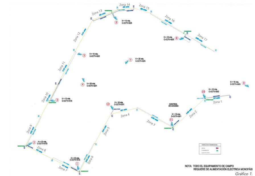
This project corresponds to a perimeter protection system consisting of 34 active infrared barriers of 4 beams and 4 Takex frequencies, arranged in 17 alarm zones with a stack of 2 barriers for each alarm zone for the detection of intruders in back to back mounting and 12 TV cameras for visual control and quick verification from the checkpoint of the nature of an alarm.
This system protects an important open-air deposit of a State property in which valuable materials are deposited in containers of great weight and whose height, length and width exceed the height of the upper infrared active barrier of the stacking of 2 barriers for each alarm zone and due to the indicated the intrusion detection technology in question was chosen. Such containers are supplied with sensors against opening and others against vandalism of the same, vibration, shock, heat.
Due to strict confidentiality requirements, the identification of such a facility is not indicated.
Personally and as Head of the Latin American & Caribbean Area of Takex I have intervened only in everything related to what corresponds to pre-sale advice, location design and frequency selection of the infrared active barriers and alignment instructions of the same, which is developed or exposed below,
Location and frequency diagramming for the stacking of 2 active infrared barriers of 4 beams and 4 frequencies for each alarm zone and alignment instructions for them
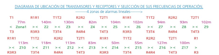
Figure 2. Diagram of location of transmitters and receivers and selection of their operating frequencies.
1) Notice the only care area is the linear section of the perimeter that correspond to its 4 linear alarm zones, zones 9,10,11 and 12. The sections of 2 zones or one do not offer any difficulty.
2) Attention; in the linear section of zones 9, 10, 11 and 12 ensure that the 5 columns of fastening of barriers in that section are aligned perfectly or on a very line of their assemblies or fixation on the ground or earth, for the optimal achievement of such alignment of all the fastening bars of zones 9, 10, 11 and 12 it is suggested to tension a guide (piolin or bale wire) between the initial clamping column of zone 9 and the end of zone 12.
3) Between each pole or each zone the stacking of 2 barriers must be of equal scope or protection distance, example;
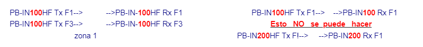
Figure 3.
4) Ensure as far as possible that all the lower barriers in all the columns are at the same height of the ground idem for the upper ones.
Alignment instructions
• All system barriers must be off or without power.
Go to the first barrier to be aligned, connect the power to that barrier only, align it according to what is indicated in the installation manual of the barrier and with the following attachments required for stacking them;
1º) Turn on the audio alignment guide. Align in a thick way through the view mirrors or optical system the upper and lower beams, from the receiver look at the internal mirror of the upper beams to see and center the vision of the transmitter of the other end, said vision centering of the opposite end requires the horizontal manual variation of the optics and sometimes the fine vertical through the fine adjustment of the vertical orientation screw of the optics. Then from the receiver of the lower beams do the same to see the transmitter centered in the internal circular mirror, the person of the transmitter must do the same as what is already indicated for the receivers through the mirror of the upper beams and then lower to see centered in their circular mirrors the vision of the receiving end. The sharper and less sonorous the alignment aid sound, the better aligned the barrier is. Almost imperceptible sound indicates optimal alignment.
Leave the alignment guide audio on. Connecting a digital voltmeter in the terminals of the receiver (monitor jack) if the final reading after alignment is 2.1 to 2.7 Vdc is fine, if it is greater than 2.7 Vdc excellent or better, if it is 2 Vdc or less it should be realigned.
Cover with the shutters the upper beams of the transmitter and receiver and align the lower beams: 1) From the receiver vary the horizontal position of the optics with the hand to the point of obtaining maximum reading. Note that this horizontal manual rotation has points with obstacles that when varying tac is heard when passing to another point another tac... etc. Observe the measurement you have, vary one point to the left if the voltage goes down back to the previous or initial point and rotate towards the first point on the right if the voltage increases, follow in that sense one more point if it goes down return to the previous point or maximum reading found and that is the correct point of horizontal alignment.
Then communicate with a handy with the person of the transmitter so that he varies this manual horizontal adjustment until obtaining the point of maximum reading.
2) Then start first by aligning the horizontal fine adjustment of the receiver and while the horizontal fine adjustment is being varied, observe the voltmeter to achieve the greatest indication of Volts in it. Be careful that the voltmeter cables are not passing through the front of the uncovered optics or the one that is being aligned, try NOT to move the body too much only the hands to avoid fluctuations of indication of the voltmeter by reflections of the infrared beams that produces the movement of the body on the receiver. Note that when varying a fine adjustment with screw if the reading increases in the direction of the hands of the clock continue turning the fine adjustment screw in that direction until maximum reading, when you are in it you will observe an area that when continuing with the adjustment in that same direction the tension does not vary, if the voltage decreases from this point, turn the screw in the opposite direction or anti-clockwise to obtain the maximum reading previously found.
Then vary the vertical fine adjustment screw and always for maximum reading, note that the procedure is the same as for the one indicated for horizontal fine adjustment.
Then tell the transmitter person to start turning the horizontal adjustment screw and according to the voltmeter reading guide him to turn the screw in one direction or another of rotation until the maximum reading position is obtained, after which instruct the transmitter person to start varying the vertical fine-tuning screw until the maximum possible reading is obtained on the voltmeter.
Attention the rotation of the screws of horizontal and vertical fine adjustments should be done very slowly that is to say varying or rotating as little as possible (minimum rotation advances - slow). Then retouch the horizontal and vertical fine adjustments on the receiver for maximum reading.
3º) Cover with the shading plate or metal attenuator with holes the receiver, be careful not to cut your hand or fingers by the sharp edges that this metal attenuator has, obvious that when the attenuator is placed in the two-beam optics of the receiver the tension will fall significantly.
Ask the transmitter person to start varying the horizontal setting minimally and observe the voltmeter reading to guide you to maximum reading. Then ask him to do the same with vertical fine tuning until maximum reading.
Then make the horizontal and vertical fine adjustments of the receiver until the highest possible voltage is obtained.
Observe what voltage was finally obtained after full adjustments with the shutter placed on the receiver. Remove the attenuator and observe that the final voltage is greater than 2 volts.
4º) cover the lower ones and align the upper ones as indicated in 1º), 2º and 3º) with attenuator
5º) cover the upper beams of the transmitter and the 2 lower beams of the receiver with the shutters and align idem to 1º) and 2º and 3º) with attenuator.
Close the Tx and then close the RX, observing when assembling or closing its lid or outer housing to close it, keeping it tight against the mounting plate to hear a beep of short duration of 1 second that confirms or ensures that the alignment of the first barrier is optimal. Open the Tx and Rx to turn off the alignment audio, disconnect the power and close the transmitter and receiver permanently so that the tamper or anti-disarm contacts are closed and as if the barrier were ready for continuous service.
6º) Go to the second barrier connect the power and do everything indicated in A) disconnect the power, go to the third barrier connect the power and align and so for all the final rest of the 34 barriers that the system has. Once they finished aligning all the barriers, connect the power to all the barriers and verify in the Alarm Center the total absence of alarms for all the zones which will corroborate the correct alignment of all the barriers such as the absence of couplings - mutual interference or crass talk between them.
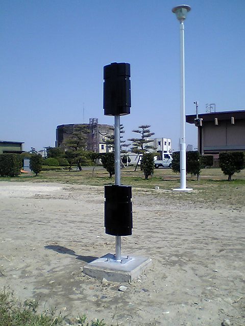
Note: The photographs used do not belong to the actual project. They are used as illustrative support.
* Eng. Basilio Angel Holowczak, Latin American & Caribbean Area Responsible, Takenaka Engineering co., LTD. - [email protected]


Leave your comment